 Common to all
models:
Common to all
models:
.All models support 8011ac radios in a 2, 4 or 6 slot
board .
.All models support backhaul frequencies:
5GHz,(e.g MD42
50),
4.9GHz (e.g. MD42
40)
2.4GHz (e.g. 42
20).
.All models are
remotely configurable. Models field
upgraded through the NMS.
MD4000
NMS User Guide
.All models support field replacement of radio cards.
.All models support an
internal GPS Radio. Must
be factory installed, requires modifications to enclosure.
.All models may be ordered in an Intrinsic Safe enclosure powered by
3.3VDC
for mining safety.
.All models support P3M
TM Persistent
Mesh. Factory default setting is P3M disabled. Enabled via NMS.

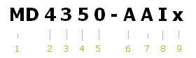
Explanation to Legend (numbers after black boxes refer to number markers above
(1,2,3 ..)
1 MD for Mesh Nodes or ME for Mesh Engines for OEM customers
who purchase flashed boards only..
2 Max Number of radios
capable of operating on the board. The MD4000 series has 4
radio slots available.
3 For MD4000 series the number of radios
actually active in this configuration- could be
1,2, 3 or 4.
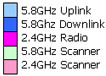
4 Frequency band of the Uplink backhaul radio (in slot 0) : 5 for
5.8GHz, 2 for 2.4GHz, 4 for 4.9GHz
5 Model Configuration. Slot 0 reserved as uplink.
Others configurable to be downlinks, AP or
scanners.**
6 Frequency band for the uplink radio, in slot 0. Typically
A (5GHz)
or 4 (Public Safety)
7 Frequency band for the downlink radio, in slot 1. bridging across freq. bands is permitted.
8 Frequency band for the service radio, in slot
2. Typically I or 4
9 Frequency band for the service radio, in slot 3.
Depends on the radio functionality.
Notes on MD4000 Model configurations (Marker #
5 above)
0 MD4350-AAIx, has 3
radios: 5.8 GHz uplink and downlink in slots 0,1 and
one 2.4GHz service in 2
MD4250-AAxx is a two radio version of the same. The
MD4xxx supports up to 4 radios.
MD2250-AA uses a two slot board with two radios up/dn in slots 0 and 1.
1 1 active radio to
perform up link, and down link in duty cycle mode. Custom configuration. .
2
MD4452-AAIA and MD4454-AAAA have
4 radios. They support two and four backhaul sub
trees
4
MD4452-AAIA and MD4454-AAAA have
4 radios. They support two and four backhaul sub
trees
5 "5" is reserved for mobility Scanner active
on the node. It may run on the uplink in duty cycle mode.
Or dedicated radio e,g. 4455-AAIA, 4355-AAxA, 4325-IIXI. See also
Single-Radio-Mesh-Options
6 MD2256-AA, using Slot
0 for uplink, downlink and slot 1 as scanner.
7 Not used
8 Legacy 4458
used three 2.4GHz or 4.9GHx Access Points. Available as
custom configuration.
9 Not used.
Standard Configurations,
4 slot radios, 4.9/5.8GHz
Backhauls, 2.4GHz Client Access
1. 4250-AAxx: 2 radios, 11ac uplink, downlink, slots 0,1.
Intended as static backhaul, no AP
2. 4350-AAIx: 3 radios, 11ac uplink, downlink, slots 0,1. 802.11bgn service on slot 2 Slot 3 empty..
3. 4452-AAIA: 4 radios, 11ac uplink, downlink, slots 0,1. 802.11bgn service on slot 2. Second in 3.
4. 4454-AAAA: 4 radios, All 11ac downlinks, slots 0,1,2, 3. Root
node, with four sectored antennas. .
5. 4455-AAIA: 4 radios, 11ac uplink, downlink, slots 0,1.
service in slot 2. 11a scanning in slot 3.
6. 4355-AAxA: 3 radios, 11ac uplink, downlink, slots 0,1. wireless backhaul only.
Scanning in slot 3.
Standard Configurations,
2 slot radios,
4.9/5.8GHz Backhauls.
7. 2250-AA: 2 radios, 11ac+11ac uplink, downlink, slots 0,1. Used as long range backhaul, sectored links, rural areas.
8. 2256-AA: 2 radios, 11ac up/dn on one radio, scanning on the other radio.
Used for mobility backhaul.